Ar dataflow
This article introduces the data flow in EasyAR Sense. EasyAR Sense uses a component-based API, where components are connected through data flows.
Input and output data
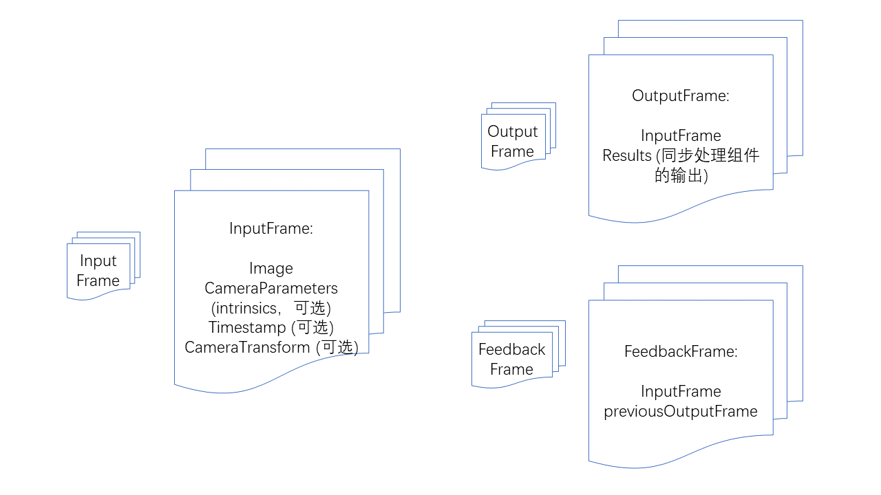
InputFrame: Input frame. Contains images, camera parameters, timestamps, camera transformations relative to the world coordinate system, and tracking status. Camera parameters, timestamps, camera transformations relative to the world coordinate system, and tracking status are all optional, but specific algorithm components may have specific requirements for inputs.
OutputFrame: Output frame. Contains input frames and the output results of synchronous processing components.
FeedbackFrame: Feedback frame. Contains an input frame and a historical output frame, used for feedback-style synchronous processing components like ImageTracker.
Camera components
CameraDevice: Default camera on Windows, Mac, iOS, Android.
ARKitCameraDevice: ARKit default implementation on iOS.
ARCoreCameraDevice: ARCore default implementation on Android.
MotionTrackerCameraDevice: Implements motion tracking, solving the device's 6DoF coordinates through multi-sensor fusion. (Only supports Android)
ThreeDofCameraDevice: Adds a 3DoF orientation to the default camera.
InertialCameraDevice: Adds a 3DoF orientation and plane-based inertial-estimated translation to the default camera.
Custom camera device: Custom camera implementation.
Algorithm components
Feedback-style synchronous processing components: Require outputting results frame-by-frame following camera images and need previous frame processing results to avoid mutual interference.
ImageTracker: Implements detection and tracking of planar images.
ObjectTracker: Implements detection and tracking of 3D-objects.
Synchronous processing components: Require outputting results per frame alongside the camera image.
SurfaceTracker: Implements tracking of environmental surfaces.
SparseSpatialMap: Implements a sparse spatial map, providing the capability to scan physical space while generating a point cloud map and performing real-time localization.
MegaTracker: Implements Mega spatial localization.
Asynchronous processing components: Do not require outputting results per frame alongside the camera image.
CloudRecognizer: Implements cloud recognition.
DenseSpatialMap: Implements a dense spatial map, which can be used for effects like collision and occlusion.
Component availability check
All components have an isAvailable function to determine whether the component is available.
Situations where a component is unavailable include:
Not implemented on the current operating system.
Dependencies required by the component are missing, such as ARKit or ARCore.
The component does not exist in the current version (variant), such as some features being absent in streamlined versions.
The component is unavailable under the current license.
Be sure to check component availability before use and implement appropriate fallbacks or prompts.
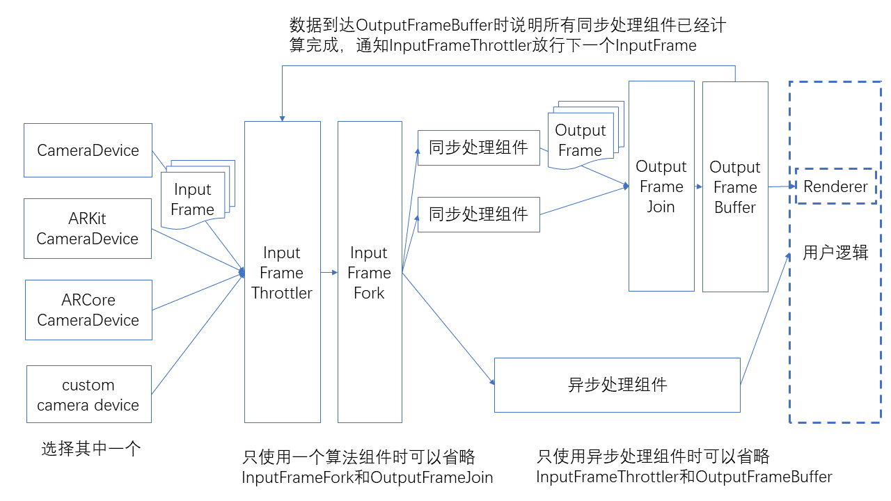
Dataflow
The connection method between components is shown in the figure below.
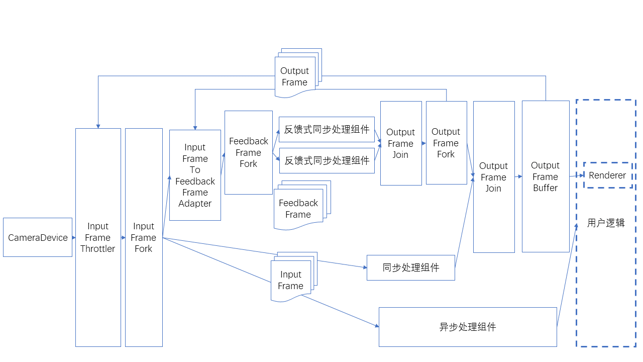
There is a special usage of feedback-style frames as input, as shown in the figure below.
Dataflow helper classes
Data flow emission and reception ports; each component needs to include these ports
SignalSink / SignalSource: Receives/emits a signal (no data).
InputFrameSink / InputFrameSource: Receives/emits an InputFrame.
OutputFrameSink / OutputFrameSource: Receives/emits an OutputFrame.
FeedbackFrameSink / FeedbackFrameSource: Receives/emits a FeedbackFrame.
Data flow branching and merging
InputFrameFork: Splits one InputFrame and emits multiple in parallel.
OutputFrameFork: Splits one OutputFrame and emits multiple in parallel.
OutputFrameJoin: Merges multiple OutputFrame into one, combining all results into the Results. Note that connections to its multiple inputs should not be made while data is flowing, otherwise it may get stuck in a state where it cannot output. (It is recommended to complete data flow connections before starting the Camera.)
FeedbackFrameFork: Splits one FeedbackFrame and emits multiple in parallel.
Data flow throttling and buffering
InputFrameThrottler: Receives and emits InputFrame, but emits only one at a time. It emits the next InputFrame only after receiving a trigger signal. When multiple InputFrame are received, subsequent ones may overwrite previous ones.
OutputFrameBuffer: Receives and buffers OutputFrame, waiting for user polling. It can emit a signal upon receiving an OutputFrame.
Connecting the signal emitted by OutputFrameBuffer to InputFrameThrottler completes the throttling process.
Data flow conversion
InputFrameToOutputFrameAdapter: Can directly wrap an InputFrame into an OutputFrame, used for rendering and display.
InputFrameToFeedbackFrameAdapter: Can wrap an InputFrame and a FeedbackFrame into a FeedbackFrame, used for feedback synchronous processing components.
Inputframe quantity limitation
CameraDevice can set bufferCapacity, which is the maximum number of InputFrame emitted; the current default value is 8.
Custom cameras can be implemented using BufferPool.
For the number of InputFrame required by each component, refer to the API documentation of each component.
If there are insufficient InputFrame, it may cause the data flow to jam, resulting in rendering stalling.
If there are insufficient InputFrame, rendering may not stall during the first startup but may stall after switching to background or pausing/starting components. Testing should cover these scenarios.
Connecting and disconnecting
Connecting and disconnecting during data flow operation is not recommended.
If connection and disconnection are required during operation, note that it can only be performed on cut edges (edges whose removal would split the data flow into two parts), not on loop edges (edges forming cycles when the data flow is viewed as an undirected graph), inputs of OutputFrameJoin, or sideInput of InputFrameThrottler. Otherwise, it may enter a state where the data flow gets stuck at nodes like OutputFrameJoin and InputFrameThrottler and cannot output.
Algorithm components have start/stop functionality. When stopped, frames will not be processed but will still be output from the component, just without results.
Typical usage
The following is the usage for a single ImageTracker, which can be used to recognize and track non-repeating planar targets.
![]()
The following is the usage for a single ImageTracker, which can be used to recognize and track repeating planar targets.
![]()
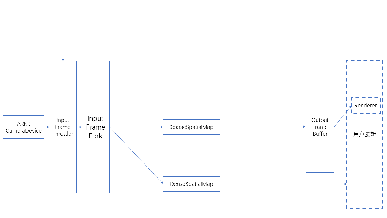
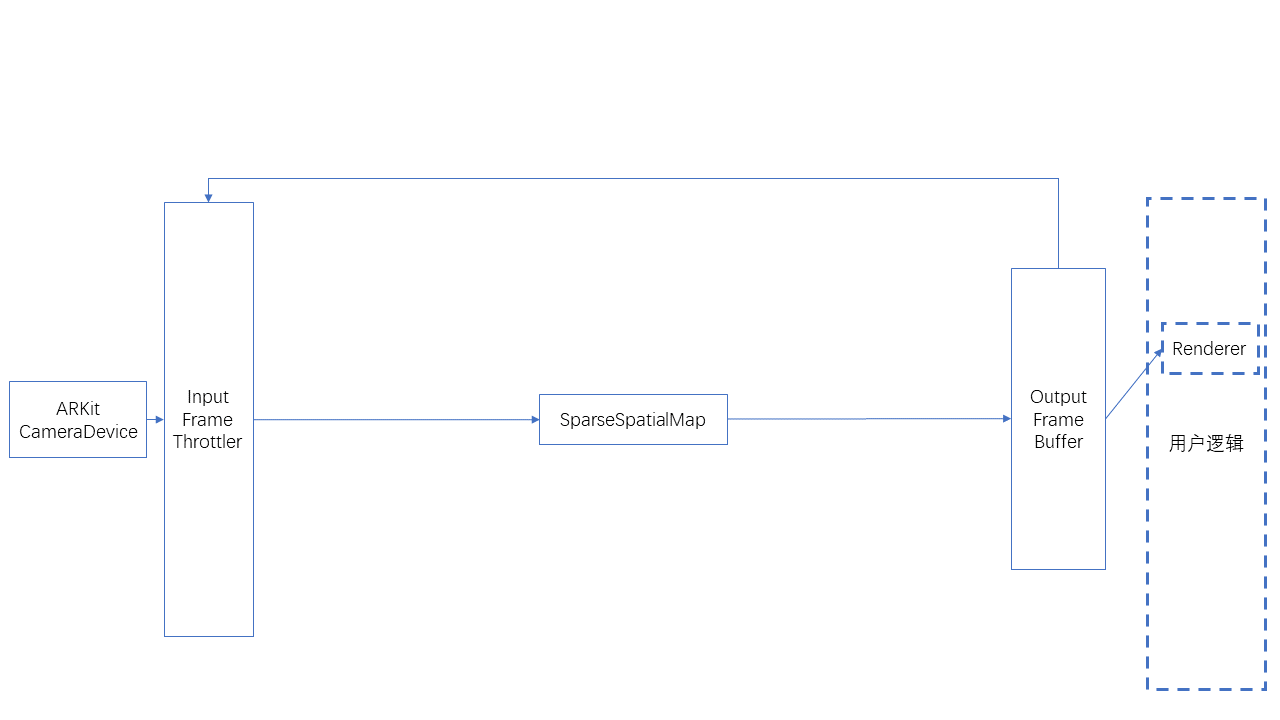
The following is the usage for SparseSpatialMap, which can be used to implement sparse spatial map construction, localization, and tracking.
The following is the usage for simultaneous use of SparseSpatialMap and DenseSpatialMap, which can be used to implement sparse spatial map construction, localization, tracking, and dense spatial map generation.